Ports Menu
Surveyor: ![]() / Express:
/ Express: ![]() / Express Plus:
/ Express Plus: ![]() / Facet:
/ Facet: ![]() / Facet L-Band:
/ Facet L-Band: ![]() / Reference Station:
/ Reference Station: ![]()
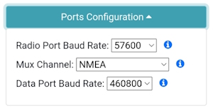
Setting the baud rates of the two available external ports
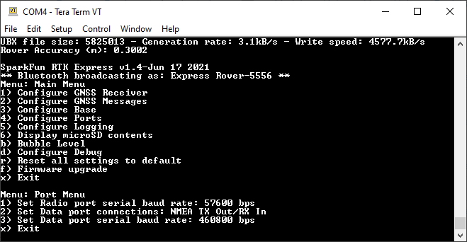
Baud rate configuration of Radio and Data ports
Radio Port
By default, the Radio port is set to 57600bps to match the Serial Telemetry Radios that are recommended to be used with the RTK Facet (it is a plug-and-play solution). This can be set from 4800bps to 921600bps.
Mux Channel
The Data port on the RTK Facet, Express, and Express Plus is very flexible. Internally the Data connector is connected to a digital mux allowing one of four software-selectable setups. By default, the Data port will be connected to the UART1 of the ZED-F9P and output any messages via serial.
- NMEA - The TX pin outputs any enabled messages (NMEA, UBX, and RTCM) at a default of 460,800bps (configurable 9600 to 921600bps). The RX pin can receive RTCM for RTK and can also receive UBX configuration commands if desired.
- PPS/Trigger - The TX pin outputs the pulse-per-second signal that is accurate to 30ns RMS. This pin can be configured as an extremely accurate time base. The pulse length and time between pulses are configurable down to 1us. The RX pin is connected to the EXTINT pin on the ZED-F9P allowing for events to be measured with incredibly accurate nano-second resolution. Useful for things like audio triangulation. See the External Event Logging section below and the Timemark section of the ZED-F9P Integration Manual for more information.
- I2C - (On Express, Facet, and Facet L-Band) The TX pin operates as SCL, RX pin as SDA on the I2C bus. This allows additional sensors to be connected to the I2C bus.
- Wheel/Dir Encoder - (On Express Plus) Connect the DATA port to the wheel tick inputs on the ZED-F9R. This aids the Sensor Fusion engine for IMU based location fixes when installed in an automobile. Signals must be limited to 3.3V.
- GPIO - The TX pin operates as a DAC-capable GPIO on the ESP32. The RX pin operates as an ADC-capable input on the ESP32. This is useful for custom applications.
Data Port
By default, the Data port is set to 460800bps and can be configured from 4800bps to 921600bps. The 460800bps baud rate was chosen to support applications where a large number of messages are enabled and a large amount of data is sent. If you need to decrease the baud rate to 115200bps or other, be sure to monitor the MON-COMM message within u-center for buffer overruns. A baud rate of 115200bps and the NMEA+RXM default configuration at 4Hz will cause buffer overruns.
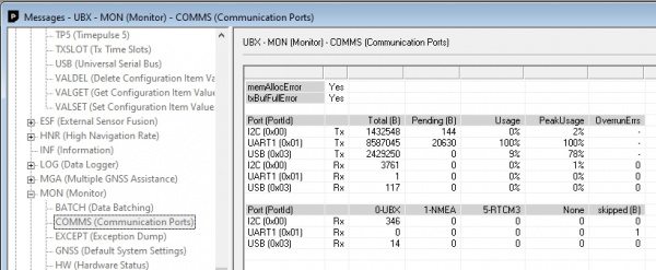
Monitoring the COM ports on the ZED-F9P
If you must run the data port at lower than 460800bps, and you need to enable a large number of messages and/or increase the fix frequency beyond 4Hz, be sure to verify that UART1 usage stays below 99%. The image above shows the UART1 becoming overwhelmed because the ZED cannot transmit at 115200bps fast enough.
Most applications do not need to plug anything into the Data port. Most users will get their NMEA position data over Bluetooth. However, this port can be useful for sending position data to an embedded microcontroller or single-board computer. The pinout is 3.3V / TX / RX / GND. 3.3V is provided by this connector to power a remote device if needed. While the port is capable of sourcing up to 600mA, we do not recommend more than 300mA. This port should not be connected to a power source.
Wheel Ticks
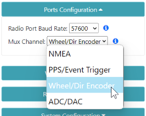
On the RTK Express Plus only. This dropdown is made available if users wish to connect wheel ticks and a direction encoder as inputs to the ZED-F9R. This aids the Sensor Fusion engine for IMU based location fixes when installed in an automobile. Signals must be limited to 3.3V.
Pulse Per Second
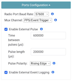
Configuring the External Pulse and External Events over WiFi
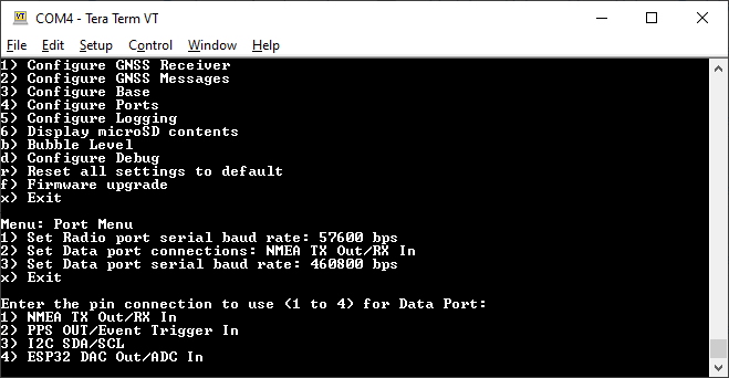
Port menu showing mux data port connections
When PPS/Event Trigger is selected, the Pulse-Per-Second output from the ZED-F9x is sent out of the TX pin of the DATA port. Once the RTK device has GNSS reception, this can be used as a very accurate time base.
The time between pulses can be configured down to 100ns (10MHz) with an accuracy of 30ns RMS and 60ns 99%. The pulse width and polarity are also configurable.
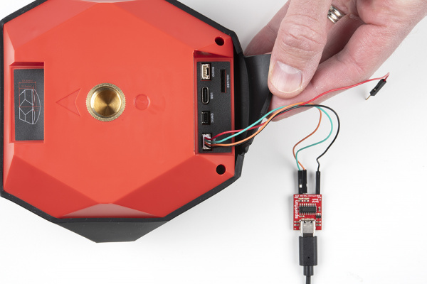
For PPS, only the Black and Green wires are needed. If you need to provide 3.3V to your system, the red wire can supply up to 600mA but we do not recommend sourcing more than 300mA.
- Red - 3.3V
- Green - TX (output from the RTK device)
- Orange - RX (input into the RTK device)
- Black - GND
Similarly, the RX pin of the DATA port can be used for event logging. See External Event Logging for more information.
External Event Logging
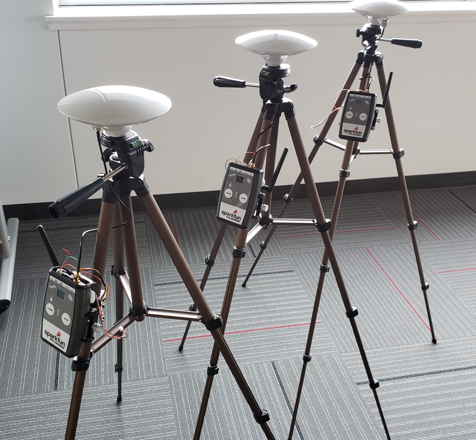
Three RTK Expresses wired with external microphones
The external triggering system is a powerful feature enabling a variety of scientific applications. Above is three RTK Expresses wired with external microphones used in a 'popped balloon' audio triangulation experiment.
The ZED-F9P has the ability to mark a detected event with +/-30 nanosecond accuracy. When enabled, an event on the RX pin (a low-to-high or high-to-low transition) on the DATA port, will trigger a message in the log with a very accurate timestamp.
- Red - 3.3V
- Green - TX (output from the RTK device)
- Orange - RX (input into the RTK device)
- Black - GND
For event logging, only the Black and Orange wires are needed. If you need to provide 3.3V to your system, the red wire can supply up to 600mA but we do not recommend sourcing more than 300mA.
Configuring the External Pulse and External Events over WiFi
Be sure to select 'Enable External Event Logging' through the ports menu.
Events within the log have the following format:
$GNTXT,numberOfSentences,sentenceNumber,CUSTOM_NMEA_TYPE_EVENT,triggerCount,towMsR,towSubMsR,accEst*CRC
For example:
$GNTXT,01,01,02,5,494326906,136292,31*74
Where
- $GNTXT: Custom NMEA text message
- 01: numberOfSentences in this report
- 01: sentenceNumber
- 02: sentenceType - Externally triggered events are type 0x02
- 5: triggerCount
- 494326906: towMsR - Time Of Week of rising edge (ms)
- 136292: towSubMsR - Millisecond fraction of Time Of Week of rising edge (ns)
- 31: accEst - Accuracy estimate (ns)
- 74: NMEA CRC
The event timestamps can be analyzed to precisely coordinate or triangulate a past event. In the case of the three RTK Expresses with microphones, the three units' locations were known with RTK 14mm accuracy. The air temperature was taken to obtain the speed of sound. From these data points, we can solve for the location of a sound such as a popped balloon.
Surveyor Data Port
By default, the Data port is set to 460800bps and can be configured from 4800bps to 921600bps.
Note: The Data port does not output NMEA by default. The unit must be opened and the Serial NMEA Connection switch must be moved to 'Ext Connector'. See Hardware Overview - Advanced Features for the location of the switch.